After a long hiatus, I've realized that my old design using Android phones will be too heavy for my next flight attempt, so I've been busy working for a year or so on a new design using some embedded chips.
Bottom line, we're still planning for an epic flight, there will still be live telemetry from the aircraft as it ascends and descends, and it will also have epic video taken from two sub-miniature 1080p cameras that should work in the cold of near space. We'll have live telemetry data streaming from the airplane via cellular modem (below about 10,000 feet) and satellite modem (anytime above that), but no way to view the video until I actually retrieve the aircraft.
This time around, I'm sticking everything into one fairly large "dart" style paper airplane. It's been hard to keep the weight down, but the body of the aircraft (paper, some small wooden reinforcements) is about 110grams, and the electronics and batteries, another ~200 grams. I've also had to lay everything out in a long, thin circuitboard, so that it will fit in the "V" of the airplane's fuselage. It's very, very tight, and unfortunately, a long, thin design is much harder to keep warm way up there. More on thermal management later.
There's a lot of equipment in a very small space, so here's a picture, and a description of the contents:
Motherboard for next generation aircraft
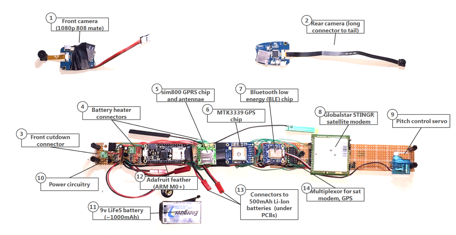
- Front camera. A very small (~8grams) "Mate" 808 camera that will go at the front of the airplane and point backwards. I need a small hole in the fuselage insulation to get the camera through, otherwise easy. These use about 300mA while working, so I need to budget how often I use them; they certainly can't be on for more than ~20% of the flight.
- Rear camera. As above, but with a longer flexible cable and a 120 degree wide angle lens. This will be mounted about 3cm above the airplane in a small tailplane to get a better forward looking view.
- Front cutdown connector. The airplane will be held to the helium balloon with fishing line, and at an appropriate altitude I'll melt it with a short length of nichrome wire driven by a darlington PNP transistor, and the airplane will drop.
- Battery heater connectors. I have two small, slim 500mAh batteries onboard to power the satellite modem and the cellular modem. Unfortunately, these perform very poorly when cold, so I've wrapped both in 100 ohms total of nichrome wire. The onboard computer polls the cellular modem's onboard temperature sensor, and if it gets below 10C, I power the nichrome wire with the 9v LiFe battery (which works well enough even when very cold). This will provide ~ 0.7-0.9 watts while turned on, and will use 100mA. Again, I'm hoping I don't need this consistently.
- Sim800H GPRS cellular modem. This is really a mini "cellphone on a chip" that cost me $9 on eBay. It uses the Ting network (really T-mobile) on an old 2G standard, but that's fast enough for me. Once in cellphone range (probably below 10,000 feet), this is regularly sending data to my server. I can also send SMS messages to it for some very basic test commands.
- MTK3339 GPS chip. The GPS brains of the device. Bought from Adafruit. Apparently this one works up to around 40,000 meters (128K feet).
- Adafruit BLEfriend. This is a Bluetooth low energy chip that can transmit telemetry to a nearby phone. I only need this for testing and pre-flight checks. I built my own android app to accept the telemetry and show red/yellow/green for the status of about 20 variables.
- Globalstar STINGR satellite modem. That's right, a satellite modem on a paper airplane. 22 grams of simplex (one way) satellite communications. I couldn't stand the idea of not knowing where the airplane is, how it's doing, etc. given the experience last time. This modem is lightweight, quite affordable, and can send multiple 9 byte messages to Globalstar's constellation of LEO satellites. These messages then get sent to my server and logged. I built a simple compression algorithm to get everything (GPS, altitude, temperature, battery levels…) into 18 bytes, and I plan to send messages every 5 minutes once the aircraft is moving.
- Pitch control servo. I'm sure it would be great to set some record for how long/far the airplane glides. I only have a limited amount of battery on board, and it's best to get the airplane down quickly. Immediately after release, the elevators will be in a "pitch up" position, and we'll film how long it takes to tumble above 100K feet before it actually flies again. This will also point the satellite modem up to maximize chances it will reach a satellite. After maybe 1-2 minutes I'll then pitch the aircraft down to descend ASAP. I'm guessing the plane will do >200 mph at high altitude before slowing down. I've a flight plan that allows for a few "pitch up and transmit" sessions, and as it gets close to the ground, the computer will pitch up hard for the last ~3000 feet so that the aircraft more or less porpoises slowly. Think of it slamming on the brakes.
- Power circuitry. There's a lot in here, but I need to convert the 9v battery into 5v to power the main computer board, and provide power to trickle charge the 1000mAh LiIon batteries at ~100mA. In an ideal world, the 9v battery will be close to exhausted by the time the flight is over, but the Li-Ion batteries will be warm and charged enough to keep transmitting for several hours until recovery.
- LiFeS 9v battery. This little square battery works really well at low temperatures, and will provide power to the main circuitry and keep the Li-Ion batteries charged as required.
- Adafruit feather M0 adalogger. This is the main brain of the aircraft. It's small, slim, runs on a 48Mhz Cortex M0+ processor, and works well. The main code compiles to around 85K now, so an Atmel chip would never handle it. There's also an SD card mounted which holds all the logging information recorded during the flight, which it then sends once it has cellphone coverage. I'm using 2 UARTs for the GPS chip, the cellphone chip, and the STINGR modem, and every single pin it has is used – it's maxed.
- Connectors to the Li-Ion batteries. Listed here because you can't actually see the batteries. There are 2x500mAh Li-Ion batteries that fit exactly under the circuitboards, which should help to keep them warm. They are connected in parallel, which is risky for high current batteries. I make sure they are the same brand and always charged to the same level before use.
- Multiplexor for the satellite modem and the GPS chip. I ran out of UARTs (serial ports) to communicate with the stuff I have, so I used a 74HCT157 multiplexor chip to switch on and off the links to the satellite modem and GPS. I can only talk to one of them at a time, but that's not a big limitation.